
Contact: John Foltz - john.foltz@usa.net
Coroplast Workshop #1
Front Fairings
We reserved a room at the Foster Community Center, in Lansing Michigan. Thanks to the Lansing Parks Department for providing the room, complete with work tables and chairs.
The workshop was held in the fall of 2000, the workshop was attended
by 8 recumbenteurs. The workshop built two fairings, one for a Lightning
P-38 (SWB) and one for a Rans Nimbus (LWB.) Unfortunately, we didn't have
an official photographer, so pics are somewhat scarce. I am supplementing
them with pics from building my own fairing, which used the same techniques.
For a copy of the accompanying handout, click
here.
| Tools
bike stand wet erase marker razor blade knife heavy scissors drill with 1/8" bit pliers hacksaw half round file duct tape glue heat gun bench vise
|
|
Several of us had pooled resources to get over Cadillac Plastic's minimum order of $100, and our base price ended up at slightly over $7.00 US per sheet, plus the share of shipping. We had about ten sheets of Coroplast in the room, 'way more than we could possibly use in a day. Once we verified we had all the materials we needed, we got to work.
SWB
Step One - The Mounts
The method for mounting the fairing to the bike is to have semi-permanently-mounted
pieces of 1" square aluminum tubing on the bike. The fairing frame consists
of 3/4" square aluminum tubing. When lined on all 4 sides with Velcro loop
material, it becomes a snug fit inside the 1" tubing, and is pinned in
place with a paper clip. The paper clip is then wrapped to the frame with
a length of Get-A-Grip.
We cut two 8" lengths of 1" tubing. For simplicity, we simply did straight cuts. Then we used a file to round one end of each to match the bike frame's contours - one for the boom tube and one for the bottom bracket shell. Finally, we drilled holes through the aluminum tubing, on the non rounded sides.
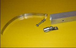
For clamps, we hacksawed three hose clamps about an inch above the worm
gear assembly. Then we used a hammer and nail to punch holes near all the
cut ends and drilled them out to accept bolts. After cleaning up the rough
edges, we mounted a pair to what would become the upright mount, and two
pairs to the front mount. The straps reach around the bike's frame and
attach to the worm gear on the other side. We mounted them to the frame,
using pieces of garden hose under the aluminum tubing and inner tube under
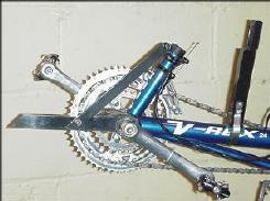
the straps. Below left is a pic of the mounts on my V-Rex. The piece running
from the top of the shift tube to the front mount is a brace, made of 3/4"
x 1/8" aluminum bar, to keep it from slipping down under the weight of
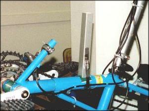
the fairing. Below center shows the pieces before assembly. Below
right, the vertical mount on the P-38 at the workshop, with no notch on
the top end. Note the different versions of notching the frame ends of
the mounts. The upright mount on the V-Rex has Velcro along the back side,
to help the Get-A-Grip hold better.
 |
|
 |
 |
Step Two - The Frame
We cut the 3/4" aluminum tubing into two 18" pieces; one for the top
and one for the front. Then, we cut the aluminum bar in half to give us
bracing for top and front. Next, we cut the angle braces. I used a piece
of 3/4" angle aluminum at the workshop, but in the pic below they
were fabricated by cutting a 3/4" long piece of square tubing and then
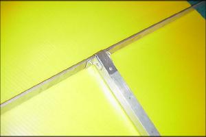
cutting the piece diagonally to yield two braces. After coming up with
four braces it was time to put everything together. Drilling, gluing, and
pop riveting the pieces, we made two Tees like the example below. The strap
around the end is 1/16" aluminum sheet; it's just there to help reinforce
the joint. A short length of the aluminum bar would do the same job, but
would be harder to form.
We bent the bracing so the top piece roughly matched the curve of the handlebars, then wrapped the front brace to curve back, leaving clearance for pedals and feet. With a strip of Coroplast in hand, we inserted the frame in the mounts, then picked the final height and forward extension so the rider (Byron) could see over the fairing and pedal without interference. We cut the frame to final length, and inserted them in the mounts. No Velcro yet, so we held it in place with duct tape.
Step Three - Shaping the Coroplast
We started with a 2" strip of Coroplast. We ran it from floor level
in front, straight up the middle and over the seat back. By pulling, we
arrived at a slope for the 'hood' that we liked, roughly trimmed it, and
taped it in place with duct tape. Same for the bottom, taping it back to
the front wheel. When we were sure we liked the curve, we punched holes
in the Coroplast and attached it to the braces with zip ties. We used the
heat gun to form the bottom section to the desired angle, softening the
inside surface then bending and letting it cool.
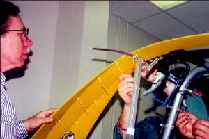
We used 6" strips for the next layer. We laid a strip along the first, determining the desired curve, then marked where they butted together, on the inside surface, using the wet erase marker. What we got was a curve on one side of the strip. Due to the highly curved front section, the mark didn't run the full length of the first or even second or third strip. The marks needed some cleaning up to produce nice smooth curves, then we a cut pair of matching strips - one for each side of the center strip, and attached them using zip ties every six inches. Here's some pics of the inside of Byron's fairing as we were building it. Notice the top brace is slightly curved, the front brace more so. You don't want the fairing to interfere with the handlebars.
 |
 |
Repeating the process, we added more strips until the fairing was fleshed out. This process produces a fairing that is wider in the middle and narrow on the ends, so we had to not only had to flesh out the top to cover the handlebars, we also ended up trimming the width at the bottom when we were done. Finally, we trimmed the top to even things up, and the bottom edge to make it nice and round.
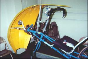
Step Four - Finishing
We put Velcro loop on the frame and made sure it fit snugly in the
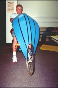
mounts. Then we moved on to taping. Frank, building the blue fairing
below, discovered why we try to keep the zip ties close to the seams;
in a few places he had run the ties across 3 or 4 flutes on each side of
the seam, and couldn't cover the entire tie with one layer of tape. That
was easily fixed, though. After running a strip of tape along all the seams
and zip tie attachments to the frame, we left it to Byron to run tape around
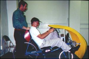
the outside edges. Oh yeah - we also clipped the tag ends on about a hundred
zip ties. Here's the semi-finished product, as Byron checks the height
one last time and Ron holds the bike. Looks fast!
LWB
The fairing for the long wheelbase was simpler than the one for the
short wheelbase, so I'll just mention a few points that were different
than those outlined above.
We ran the LWB fairing from the front tire to the top of the handlebars. At the bottom, we used short pieces of aluminum bar, notched at one end for inserting into the front axle Q/R, and used the pliers to twist them. We eventually pop riveted them to the side Coroplast strips. At the top, we zipped a Coroplast mount to the handlebars. This meant that the fairing was not easily removable, but Frank didn't care, as he either rides from home or transports it inside his van.
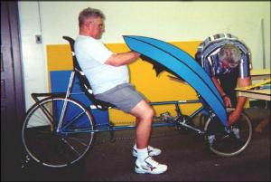
Here is the only pic I have showing the fairing in its early stages. With 6 penny nail in hand, I prepare to punch holes for the final zip tie attaching the first side panel to the center strip. Jun helps hold the pieces and Frank supervises. You can see two other zip ties in place; one almost under Frank's finger, the other about halfway down. They're pretty inconspicuous, unless you're up close. The duct tape is holding the center strip to the tire at this point.

Below left: Frank checks the height while Tom adjusts the mounts. Below right is the front view. You can see the 'billow' effect, which could be minimized by fleshing out the outer strips at top and bottom. The narrow center strip minimizes the amount of fairing presented flat to the airflow. Come to think of it, once the adjacent panels are cut, the middle piece could be eliminated, leaving the fairing to angle to a point.
 |
 |