1.
2.
3.
4.
One thing I really didn't like about my Baron was the crummy accomodation for routing the power side of the chain under the seat. This location has high stress, and the chain has to deflect about 30 degrees. The chain, which was not the same profile as a belt, clattered over the plastic pulley's smooth belt groove, and, being a bit harder than your standard belt, tore up the groove's bed in short order. A sprocket was called for, and if aluminum was unavailable, even a heavy steel one was better than replacing a plastic pulley every 500 miles.
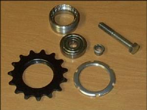
It was Cary Chen who put me on the right track by suggesting a drive sprocket from a track bike. Rather than try to describe it, here's a few pictures. First, picture 1 shows the parts that I am using. Top, a UN-52 left-hand shell. Below that is a #6200 cartridge bearing, (two needed,) and below that are the 15 tooth sprocket and bottom bracket lockring. Alongside the bearing is a chainring nut, the counterpart to a chainring bolt, (two needed,) and to the right is the 8mm bolt which held the previous rollerblade wheel-based idler. You're going to want a 1" shoulder on the bolt, because the assembly as shown will be 7/8". Then, use washers or a chainring spacer to take up the remaining space. A #6200 bearing has a 1/2" bore, whereas I needed a 8mm or 5/16 bore for the bolt, which is why I needed the chainring nuts. The chainring nuts have been drilled out to 5/16", just enough to remove the threads, and fit tightly into the bore of the bearing.
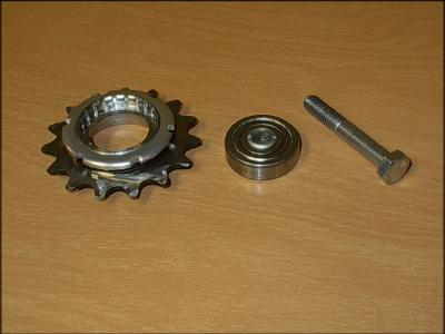
In picture 2, I have assembled the sprocket and lockring on the
shell, with the back side of the sprocket facing up. I have also inserted
the chainring nut into the bearing. As you can make out in the picture,
I had to grind the backside of the sprocket a little bit. The 9 speed chain
is just a nudge too narrow for the sprocket otherwise. Next time, I'll
buy a 9-speed sprocket! When I install the bearings, I will put the chainring
nuts toward the middle of the assembly; that way they will butt up against
each other and help support the 'pinching' force of bolting it onto
the bike. Later, I will get some bluing compound and treat the bare metal
to resist corrosion.
|
1. |
2. |
|
3. |
4. |
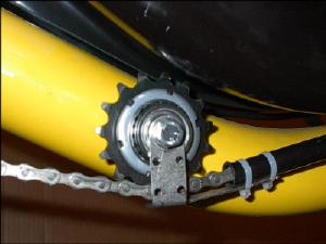
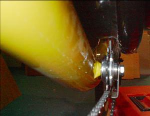
Picture 3 shows the assembly on the bike, in place of the original pulley. Now, doesn't that look nice? I've fiddled with the placement and orientation of the sprocket on the shell to get a nice straight line into the chain tube, and now the lockring is on the outside. The 15 tooth sprocket is almost exactly the same diameter as the original pulley's groove. In picture 4 you can see there is plenty of side clearance to the seat. I took up the extra space on the bolt's shoulder by shimming the frame side of the inner bearing; placing washers on the outer side would increase the seat clearance at the expense of a bit more parallax to the cassette.
There is a fair amount of torque exerted on the sprocket while pedaling. With the sprocket and lockring oriented as shown, the torque on the sprocket is such that it will try to unscrew itself. I've had good luck by using Threadlok and tightening the heck out of it, but the obvious solution is to flip the whole thing over, putting the lockring on the frame side. Then, pedaling will tend to tighten it ever more.
Cost for the assembly was $11.84 for two bearings, plus $5.00 for the sprocket, lockring, and shell. The trip to my workshop's parts tray for the other stuff was free.